Portable QRP Multi-band CW TRX
THis page describes the first revision of this TRX. Revision 2 is out now.
Here, I like to present my small portable QRP CW TRX, that I frequently use at home as well as outdoors, e.g. on bicycle tours. Hence the design constraints were: small size and light weight, low power consumption, CW QRP rig and at least 3 bands. For example, a night band (e.g., 40m) a day band (e.g., 20m) and a contest free band (e.g., 30m).
To this end, one of the mountain-topper rigs by LNR precision would be an ideal choice. However, in my opinion they are prohibitively expensive ($250 +). A much cheaper alternative would be a QCX from QPR Labs ($50). This transceiver, however, is only a single-band rig. Hence, I thought about designing a multi-band version of QCX, as it will not only match all my requirements, but also entertains me more than just building a kit.
Features
Finally I got a portable QRP CW rig with the following features:
- Multi-band, covers 80m, 60m, 40m, 30m, 20m, 17m and 15m.
- QRP output power between 2W and 8W (at 13.8V), depending on how the output-transformer is wound.
- Can and has been operated several hours continuously with 10 NiMh 1.2V @ 2.1Ah cells, generating between 5-7W RF output.
- Reasonable sensitive direct conversion receiver with unwanted side-band suppression. I do not have the equipment to actually measure the RX performance. In a direct comparison with a 20m QCX, my design appears to be at most a few dB worse.
- Reasonable unwanted side-band suppression. Like the QCX, this design can achieve almost perfect unwanted side-band suppression on a single band. Over several bands, however, a compromise must be found to provide a reasonable unwanted side-band suppression over all bands. In the end, the unwanted side-band suppression is satisfactorily even on busy days.
- Build-in automatic keyer, battery monitor etc. As I need to switch the LP filters for several bands, I loose some features of the QCX. For example, you may need signal generator (e.g., another QCX) for tuning the unwanted side-band suppression. All operation critical features like split, RIT, etc. are present.
Circuit description
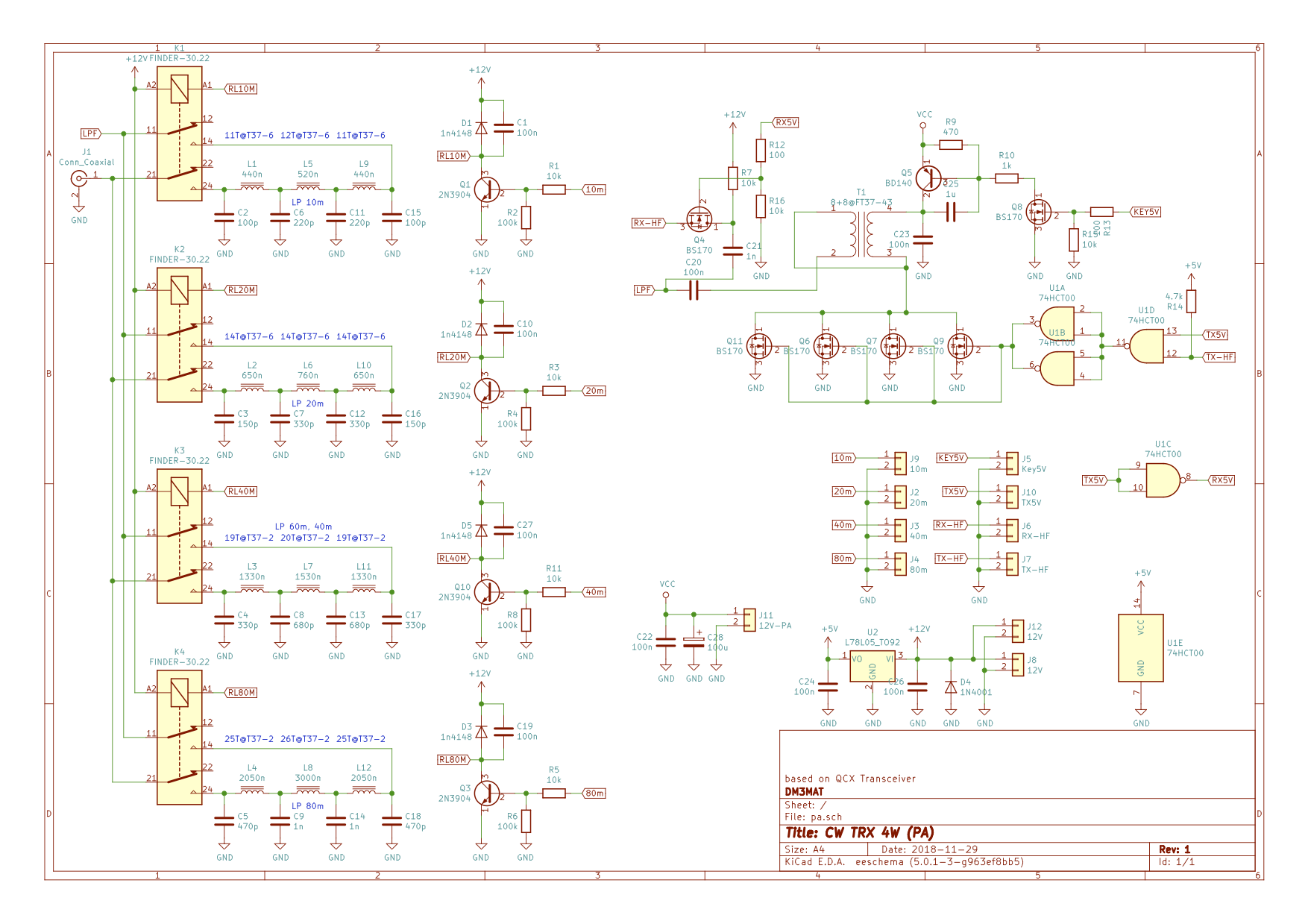
A pure CW rig allows to build very efficient PA stages, that can be driven by a simple and cheap TTL circuit. That is, a class C (or sometimes also called a class D) PA. Moreover, the efficiency of these hard switching PAs imply, that there is no need for cooling of the PA transistors at output powers between 5-10W. The transmitter design was therefore complete: A SI5351 chip generates the RF buffered by a TTL driver (e.g., a 74HCT00). The PA will consists of several BS170 MosFETs. Keying and key-shaping will be provided by a simple BD140 PNP transistor, in-line with the PA output transformer. The rich harmonics of the PA will be reduced by a three-stage lowpass filter.

To this end, the transmitter design differs only slightly from the design of the QCX: Several low-pass filters switched by relays, in contrast to a single LP of the QCX. A broad-band output transformer at the PA transistors in contrast to the tuned output transformer of the QCX. The latter (tuned) output transformer has the advantage of compensating for some output capacity of the PA MosFETs, increasing the efficiency further (so-called class "E" PA) while restricting the PA to work only on a single band. Using a broad-band transformer, the PA will not achieve this high efficiency but will work on many bands.

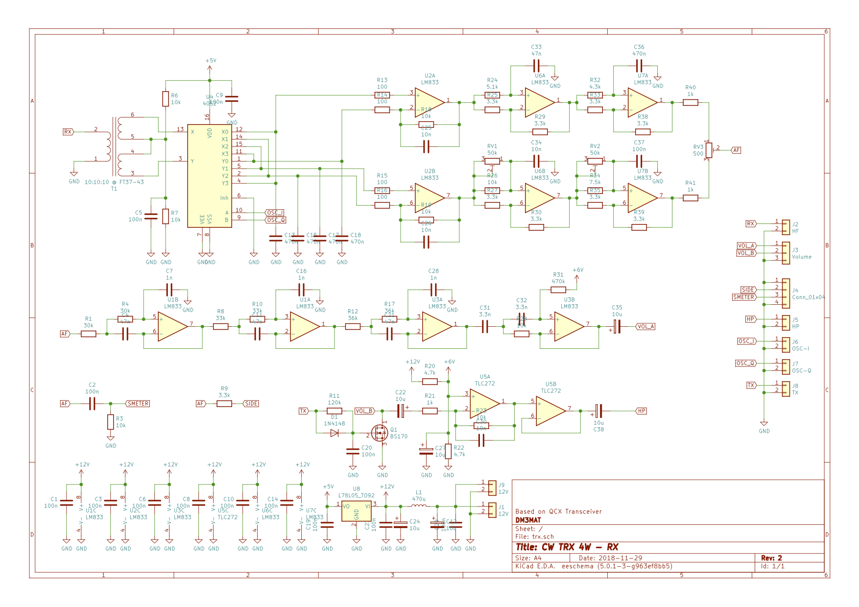
The receiver design was then basically copied from the QCX as the receiver is almost able to work on all bands. In the QCX receiver design, there is a narrow band-pass filter at the receiver input. This band-pass filter is the only part in the receiver design that limits the QCX to receive on a particular band. In my opinion, this band-pass is not really needed: The major issue of the receiver design of the QCX (using fast CMOS-switches as mixers) is low suppression of harmonically related mixing products. That is, if you tune such an RX on e.g. 7Mhz, you will also receive on 14Mhz, 21Mhz, 28Mhz, ... . Unless you are in a very noisy environment, intermodulation should not be an issue, as these mixers are incredible linear with respect to the RF input signal (i.e., low IM) but incredible non-linear with respect to the LO signal (i.e., low harmonic suppression). The PA low-pass filters, however, remain in the reception path while receiving and therefore, suppress the harmonics heavily. Hence, I decided to remove the RX band-pass filter and to replace it with broad-band RF transformer. The rest of the receiver design remains similar to the QCX. Unfortunately, it is now difficult to source the FST3253 with an SMD package, that can be hand-soldered. I resorted to a cheap 74HC4052 switch, which has the major disadvantage of having a high Ron compared to the FST3253. This amounts to a loss of about -6dB compared to the FST3253. Being a QRP rig, however, implies that the opposite side needs the good receiver.

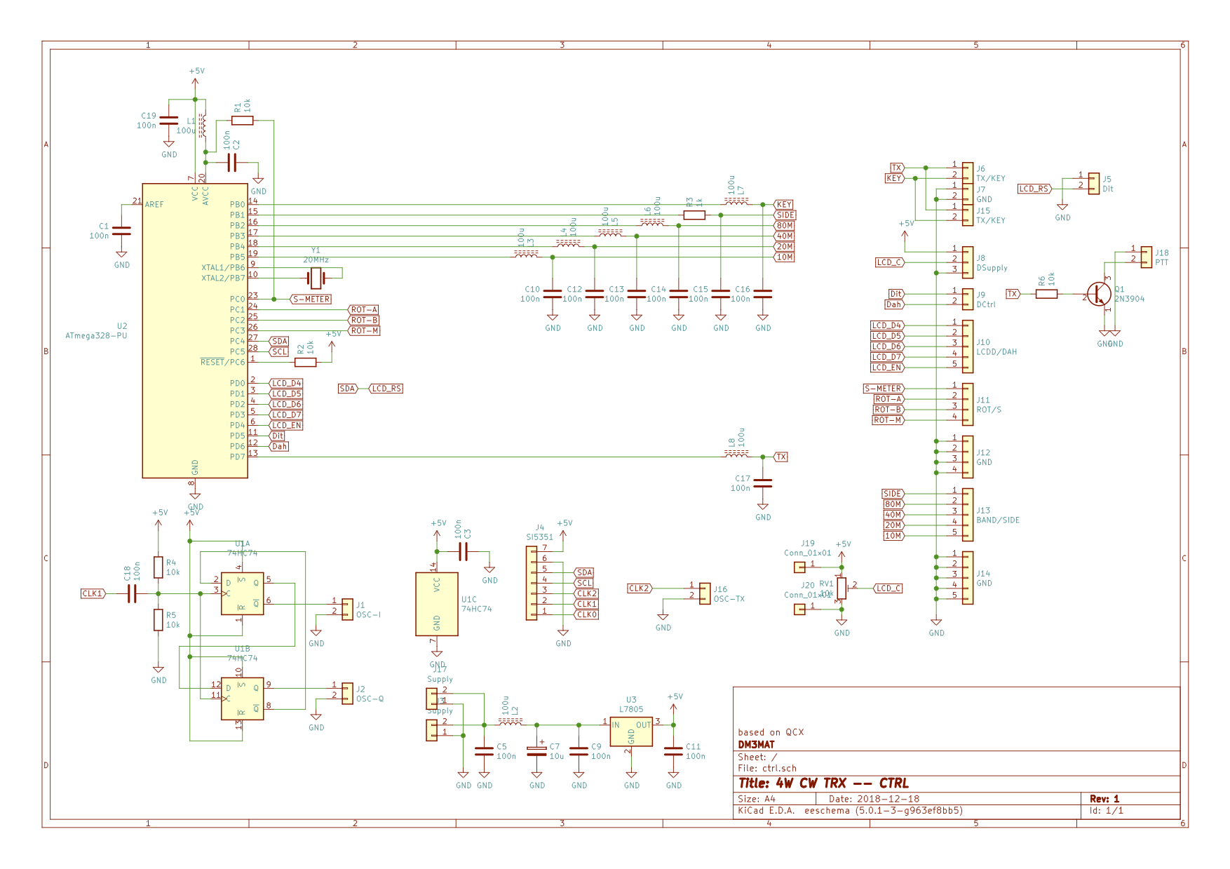
The last difference to the QCX is the I/Q frequency generation of the phasing receiver: The QCX uses a clever trick to generate the 90deg phase-shift directly using the SI5351 PLL chip. For my circuit, I resorted to the typical divide-by-four technique using a 74AC74.
Sources
The source code, that is, including the schematics, board layouts and firmware as well as an assembly manual in German, can be found on my Github repository.
Best and 73,
Hannes, DM3MAT