Small 80m Foxoring transmitter
Foxoring is a variant of ARDF, where many very low power transmitters are hidden in the field. These transmitters have a very short range (about 100m) and send continuously. Each participant gets handed a map where for each transmitter, a position is marked where the transmitter can be received. The participant then has to find the exact position of the transmitter.
As these transmitters send continuously, foxoring might be ideal for those trying ARDF for the first time.
Circuit description
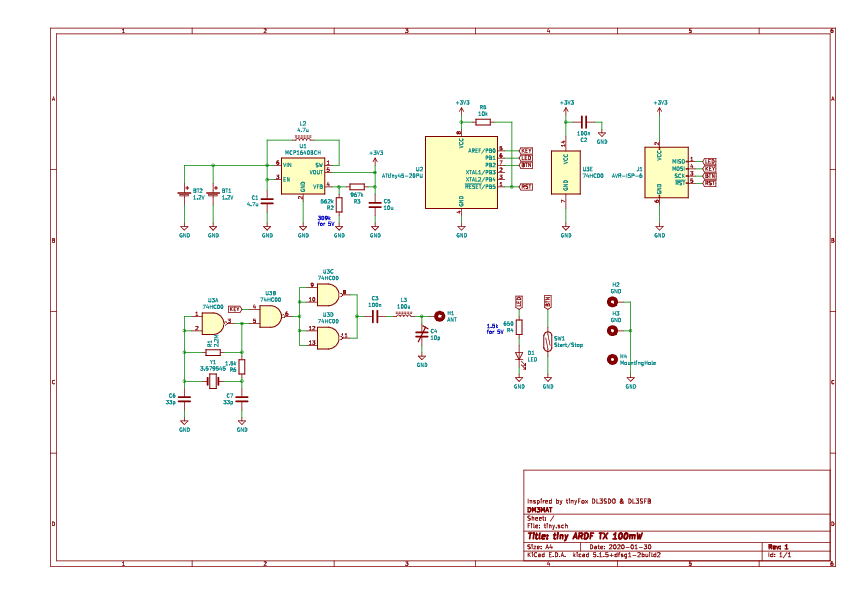
The circuit consists of a boost converter that increases the 1.2V battery voltage of a single-cell AA NiMH battery to either 3.3V (R2=562k, R4=650) or 5V (R2=310k, R4=1.5K). The Oscillator consists of a 3.579MHz crystal and one NAND-gate of the 74HC00 (IC 3). Two other NAND-gates of the latter IC also act as the PA keyed by the ATTiny 45 MCU (U2). L3 and C4 act as an L-match trying to match the 50-60cm long telescope antenna to the PA (do not expect much). That latter is a cheap telescope antenna that can be obtained easily at HAM swap-meets or at ebay.
There is no on-off switch. That means, the transmitter switches on as soon as a battery is inserted. The transmitter, however, does not immediately start to transmit. It boots into idle-mode indicated by a blinking LED. The reed-switch SW1 can then be used to enable/disable transmission using a magnet. It is therefore not necessary to open the watertight chassis to control the TX. When transmitting, the LED with key along.
Mechanical assembly
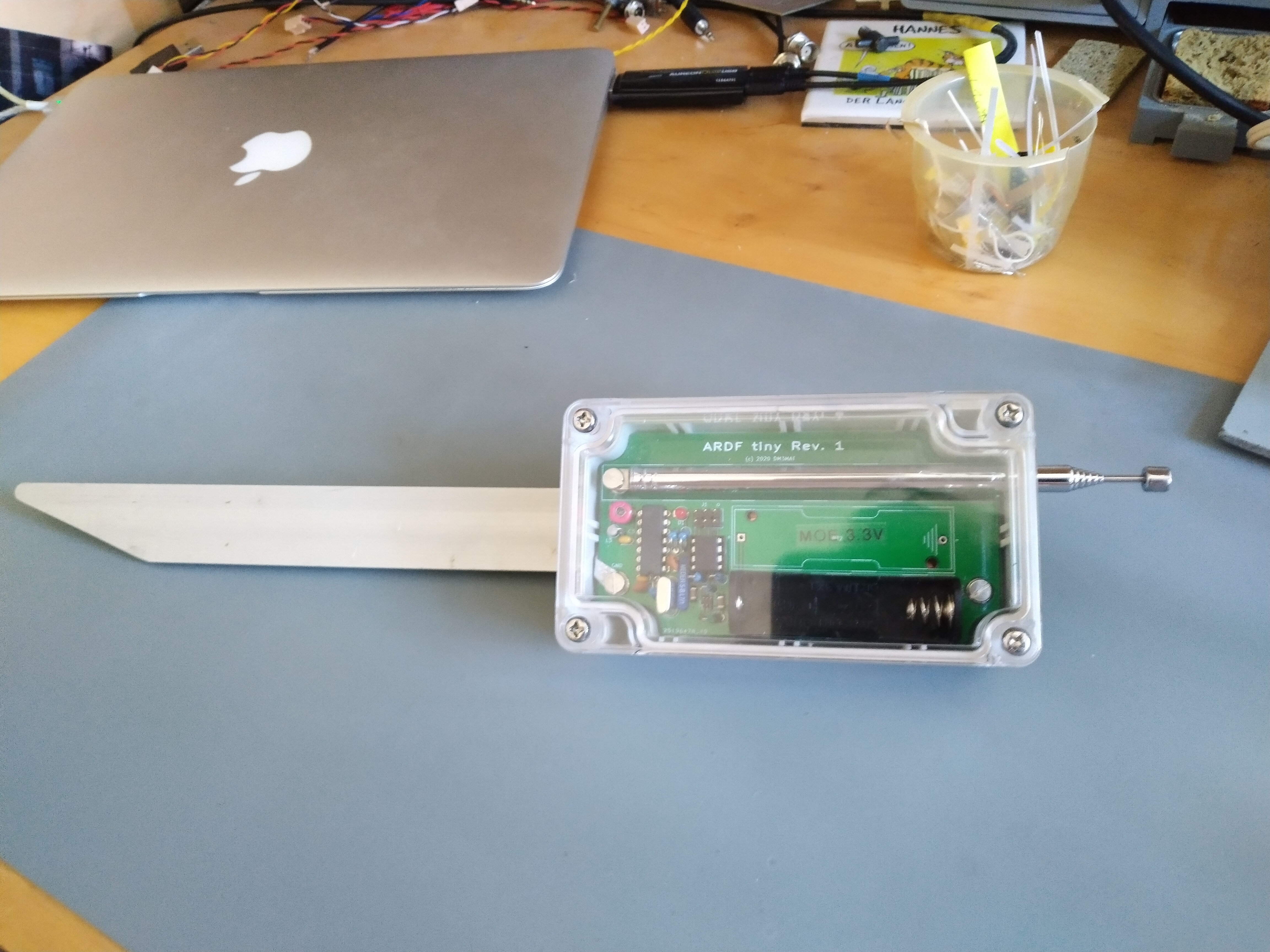
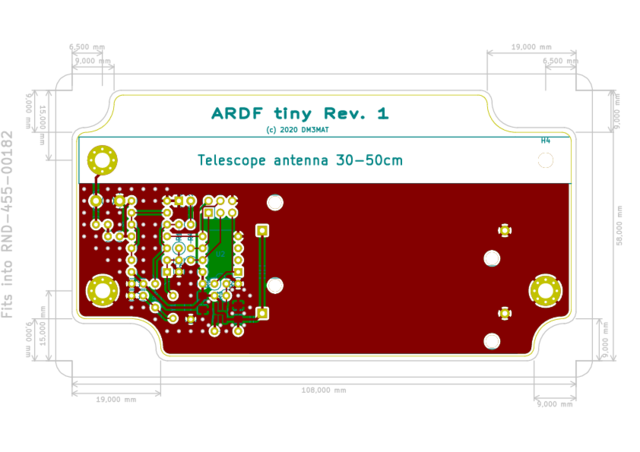
The whole design was aimed at easy deployment and ruggedness. That is, a robust and watertight chassis was chosen (RND-455-00182) and the board was designed to fit snugly into it. The grounding rod is mounted directly onto the chassis such that the complete assembly can be pushed into the ground and is ready to go.
A hole must be drilled into side of the chassis to put the antenna through it. The antenna is then directly screwed to the board. To make everything watertight silicon might added there.
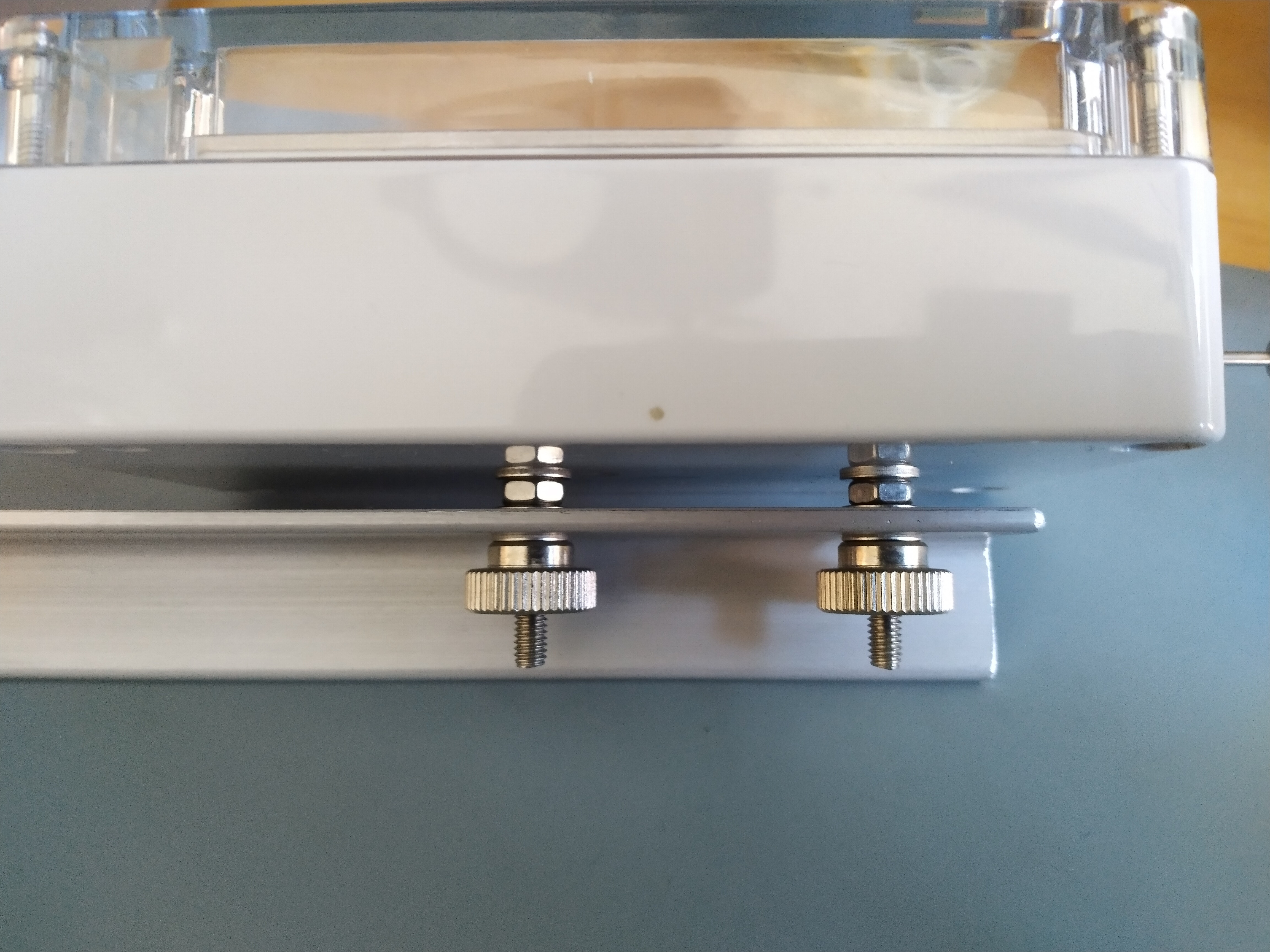
The grounding rod is mounted on the backside of the chassis. Please use countersunk screws to mount the grounding-rod. There is not much space between the board and these screws. Use some soldering whig to connect the grounding rod to one of the two mounting holes on the board labeled GND.
Firmware
The firmware sources can be obtained from my GitHub page. A programming header for the ISP is on the board.
Best & 73,
Hannes, DM3MAT