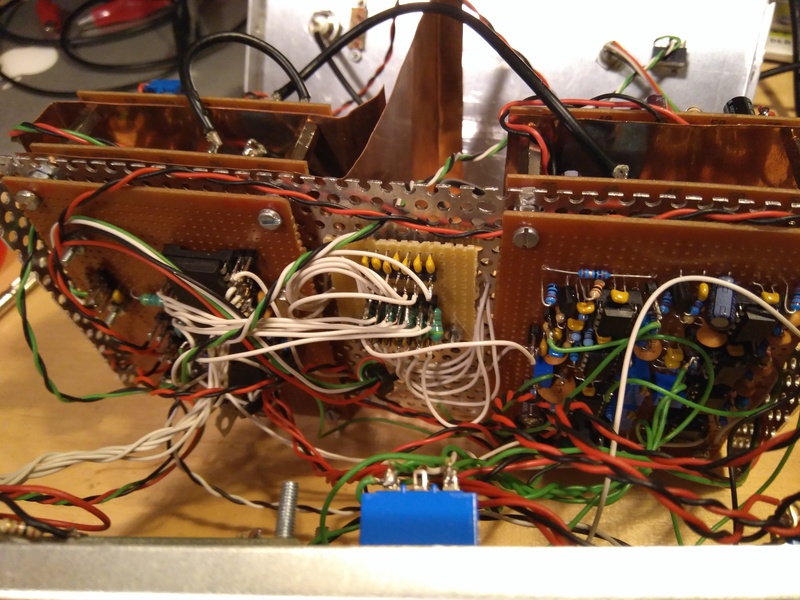
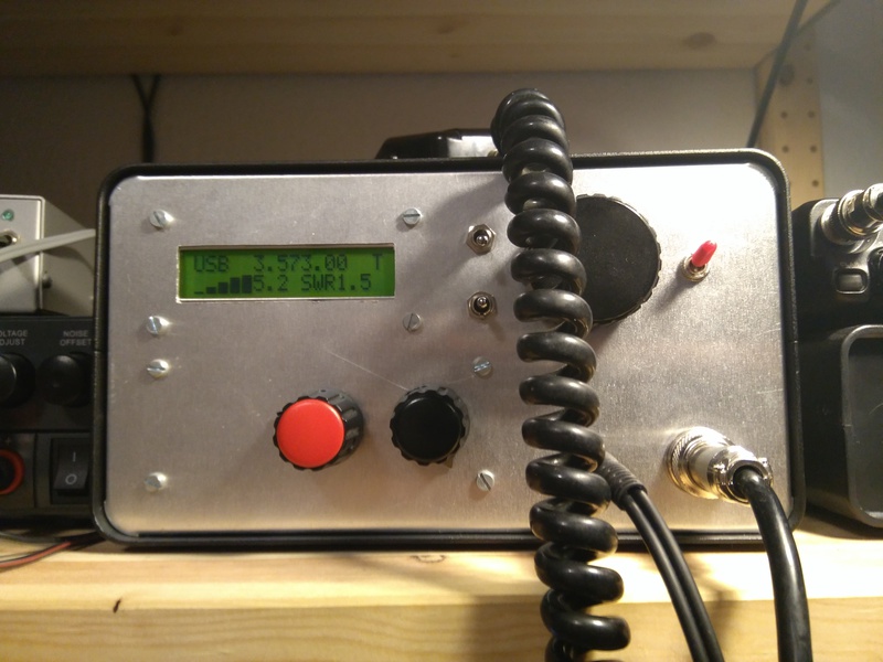
A multi-band SSB QRP TRX
Inspired by a design by SP5AHT, I wanted to build a multi-band SSB rig as my first TRX design (a bit bold, I know). The SP5AHT design is a super-het using only two SA612 ICs. The SA612 ICs implement a Gilbert-cell mixer and therefore have defined inputs and outputs. In contrast to the popular diode-ring mixers, the same Gilbert cell cannot be used as a product detector and SSB exciter that easily. SP5AHT, however, came up with the idea, to swap the VFO/BFO oscillators when switching from RX to TX and thus allowing to use the same Gilbert cells in a super-het design for receiving and transmitting. Together with the popular SI5351 PLL chip, which provides at least two independent and freely programmable outputs, this design is easy to realize. Together with a hybrid-cascode IF amplifier with AGC, my SSB TRX design was born.


To save space and cost, a single homebrew SSB crystal filter at 20MHz was chosen and an additional active audio CW filter provides the desired selectivity for CW. In fact, the CW transmission is just the CW side-tone transmitted via SSB! The PA was inspired by the popular uBitX TRX and delivers 10W-5W (2.5W at 30Mhz) over all shortwave bands using the inexpensive IRF510 Mosfets in a push-pull configuration.
Features
- All-band QRP TRX (160m - 10m) with 10W output on 160m-40m, 5W on 20m and about 2.5W on 10m.
- SSB, CW and Digi modes.
- Microphone compressor (really).
- Super-het receiver with AGC (take that uBitX).
- Narrow active CW audio filter.
- Build-in proper SWR & Power meter.
- All the usual bells and whistles like split, RIT, clearifier, automatic keyer, etc.
Receiver/Exceiter
As mentioned above, the receiver and SSB exciter consists of two SA612 (IC1 & IC2), the SSB crystal filter (XTAL), IF amplifier (Q7, Q9, Q10).

The relay K1 acts as the receive/transmit switch. The RX path then starts from K1 through the auto-transformer U2 and pre-amplifier stage Q8 into the first mixer IC1. When receiving, the VFO signal is connected to the first mixer IC1. The IF signal then enters the crystal filter (XTAL) through the transformer U4. The filtered IF then enters the IF amplifier stage. That stage is a hybrid cascode amplifier with AGC. This amplifier circuit was adapted from the popular circuit by W7ZOI and WA7MLH (QST, Dec 2007). The amplified IF then enters the product detector IC2. The resulting audio signal leaves the circuit through the low-pass filter L2+C12.
The transmit path, however, starts at IC1. The audio signal enters the exciter through the low-pass filter L1+C9. Here the BFO signal is connected to IC1. The generated DSB signal then enters the IF amplifier through the the crystal filter. The mixer IC2 then shifts the IF frequency to the desired transmit frequency. Finally, the SSB signal leaves the circuit through the transimpedance amplifier T1+T2 and receive/transmit switch K1.

The IF frequency here is 20MHz and thus lower than the highest operating frequency. To avoid band-pass filters for all bands, I stole a trick from the Minima TRX by VU2ESE (Farhan, uBitX). For frequencies below 20MHz (i.e., 1.8-14MHz) a simple low-pass filter is sufficient to suppress the mirror frequency and leaking IF. For frequencies above 20Mhz, the mirror frequency would lay above 60Mhz. To suppress the mirror frequency, a simple 30MHz low-pass filter is sufficient. The IF, however, could leak through that filter. Hence 3 20MHz traps where added to the low-pass filter to filter out the IF.
Audio section
There is a lot of stuff in the audio section.

IC4B is a 300Hz-3kHz active audio band-pass filter for SSB. IC4A, IC5A, IC5B form a 3 stage active audio band-pass filter around 650Hz for CW. The selected audio signal gets finally amplified using the famous LM386 (IC6). IC8 & IC1 form the AGC circuit that controls the gain of the IF stage above. IC1B amplifies the audio signal and is also a precision peak-detector, IC1A is then just a buffer.
The audio from the microphone (dynamic) gets amplified by IC2B and buffered by IC7A. IC2A together with T1 and Q1 acts as an audio limiter/compressor for the microphone signal. IC7B then is just a narrow band-pass filter for the PWM side-tone to get a clean 650Hz side-tone.
PA, LP and SWR meter

The PA circuit is more or less directly stolen from the uBitX. The PA consists of two pre-amplifier, one driver and one final stage. The latter consists of two IRF510 in push-pull configuration. So, nothing special here.

Except for the SWR/PWR meter circuit at the output of the low-pass filters, there nothing special about this section.
Controller section

The controller section just contains a fat ATMega32 (DIP-40) controller with an SI5351 breakout board.
Sources
Not yet, I have to clean up that directory. I may also convert the Eagle CAD files to KiCad.
Best & 73,
Hannes, DM3MAT